

Understanding line vs load wiring helps you read switches, GFCIs, thermostats, disconnects, and other electrical devices correctly. Line generally brings electrical power into a device. Load carries that power from the device toward equipment or other outlets.
Direct answer: Line is the incoming power side of an electrical device, usually supplied from the breaker panel. Load is the outgoing side that carries power toward a light, appliance, heater, motor, or downstream receptacle. On GFCI receptacles, connecting these sides correctly also determines which downstream outlets receive protection.
| Feature | Line | Load |
|---|---|---|
| Main purpose | Brings power into a device | Sends power toward connected equipment |
| Typical source | Breaker panel or upstream circuit | Device’s output side |
| GFCI role | Powers the GFCI itself | Can protect downstream receptacles |
| Required on a GFCI | Yes | Only when downstream protection is needed |
| Common label | LINE | LOAD |
| Identification | Trace or test the incoming supply | Identify the outgoing circuit after the device |
Key Takeaways
* LINE usually means the incoming electrical supply. * LOAD usually means the circuit leaving a device toward equipment. * A GFCI needs incoming power connected to its LINE terminals. * GFCI LOAD terminals can extend protection to downstream receptacles. * Terminal positions can vary between manufacturers. * Always follow markings and manufacturer instructions rather than assuming terminal positions.
What Do Line and Load Mean in Electrical Wiring?
The word line describes the supply side of many electrical devices. It normally receives power from a breaker, panel, disconnect, or another upstream device. Think of it as the electrical path entering the equipment.
The word load describes what receives power after that point. A load might be a lamp, motor, heater, appliance, receptacle, or another circuit section. The term can describe both the powered equipment and the outgoing connection feeding it.
This distinction appears throughout residential and commercial electrical systems. You may see these labels on GFCIs, switches, thermostats, contactors, disconnects, and control equipment. The exact wiring arrangement still depends on the particular device.
Line vs Load: The Most Important Differences
The simplest distinction concerns the direction of power flow. LINE is generally upstream, while LOAD is generally downstream. That difference becomes especially important on protective electrical devices.
A regular mechanical switch may interrupt power between the supply and a light. Some electronic switches need a specific incoming connection because their electronics require constant power. Always check the device diagram before moving existing conductors.
GFCI receptacles make the distinction even more important. Their LINE terminals accept the incoming circuit conductors. Their LOAD terminals can supply other receptacles through the GFCI’s protection.
Line Is the Incoming Supply
A line conductor brings electrical energy from the source toward a device. In a typical home branch circuit, that source is ultimately the electrical panel. Another upstream outlet may sit between the panel and the device.
The conductor colors alone cannot always prove which cable is incoming. Both incoming and outgoing cables may contain black, white, and ground conductors. Existing installations may also contain unusual or modified wiring.
For that reason, identify conductors by function rather than color alone. A manufacturer’s wiring diagram should remain the primary reference. Complicated or uncertain circuits are better handled by a qualified electrician.
Load Is the Outgoing Side
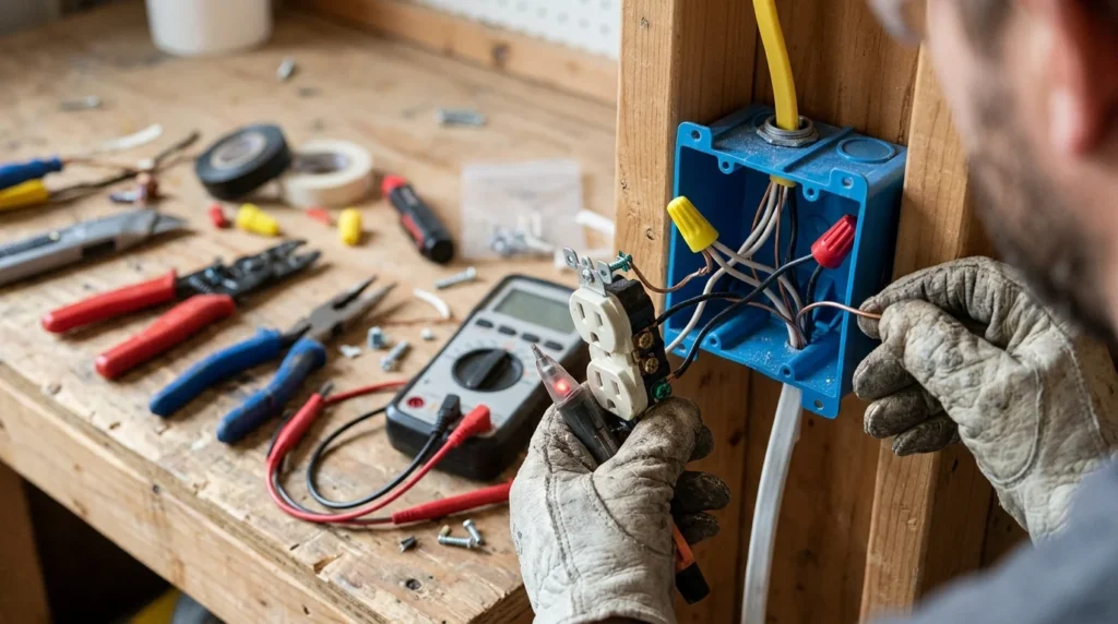
The load side supplies whatever operates after the control or protective device. That equipment could include a light fixture, heater, receptacle, or appliance. It might also include several outlets located farther along one branch circuit.
Not every electrical device uses separate LOAD terminals. Standard receptacles, for example, can be wired through several approved configurations. Protective devices often make the distinction more explicit.
Physical location also does not prove electrical order. An outlet farther across a room is not automatically downstream from another outlet. The actual cable routing determines their relationship.
How Line and Load Work on a GFCI Outlet
A GFCI receptacle usually has terminals clearly marked LINE and LOAD. Connect the incoming hot and neutral conductors to the LINE terminals. The LOAD terminals are used when additional downstream outlets need GFCI protection.
Many new GFCI devices arrive with the LOAD terminals covered. That covering helps prevent accidental use during a basic installation. Leave those terminals unused when downstream protection is unnecessary.
When LOAD terminals are used correctly, one GFCI can protect connected receptacles farther along the circuit. This arrangement is common in homes. Those downstream receptacles should be identified according to applicable installation requirements.
Leviton and Lutron manufacturer instructions describe this same basic arrangement. Their product instructions specify incoming power on LINE and downstream wiring on LOAD. Always use the instructions supplied with your exact device.
What Happens If Line and Load Are Reversed?
Reversing the connections can prevent a protective device from working as intended. Many modern GFCI receptacles are designed to resist resetting when supply conductors are connected incorrectly. That behavior can help expose an installation error.
Older equipment may behave differently, so visible power does not always prove correct wiring. Testing must follow the manufacturer’s instructions. Never assume a receptacle is protected simply because connected equipment operates.
Incorrect wiring can also confuse future troubleshooting. A later homeowner or electrician may expect labeled terminals to match their intended functions. Correct identification makes the circuit safer to service and understand.
How Can You Identify Line and Load Wires?
Start with the device markings and the existing circuit layout. If the wiring is already labeled accurately, those labels provide useful information. You should still verify the circuit before relying on old markings.
A box containing one cable may have only an incoming supply connection, depending on the application. Boxes containing several cables can be considerably more complicated. They may include branches, switch legs, shared neutrals, or multiple circuits.
Manufacturer procedures sometimes describe controlled testing methods for identifying incoming power. Such procedures can involve exposure to energized circuits during part of the test. People without electrical training should not perform live diagnostic work.
A licensed electrician can identify the circuit with the right meters and safe testing procedures. This is especially valuable when wires are damaged, unlabeled, modified, or difficult to trace. Professional help also reduces the chance of confusing separate circuits.
Line and Load on Switches
Traditional single-pole switches are simpler than GFCI receptacles. One conductor supplies power to the switch, while another carries switched power toward the light. These functions broadly correspond to the supply and load sides.
Some basic switches may operate regardless of which two switching terminals receive those conductors. Electronic switches can have specific LINE and LOAD leads. Smart switches may also require a neutral conductor.
Always follow the printed diagram for the model being installed. Do not transfer conductors based solely on their positions on the old switch. Manufacturers can use different terminal arrangements.
Electrical work also connects closely with wider home-safety planning. Tablogy’s guide to budget-friendly security solutions for schools discusses lighting and electrical security improvements. Safe installation remains important whenever powered equipment is added.
Line and Load on Thermostats and Heaters
Line-voltage thermostats commonly use line and load terminology. LINE connects to the incoming electrical supply. LOAD connects toward the electric heater or other controlled equipment.
This setup differs from low-voltage HVAC thermostat wiring. Low-voltage systems use control circuits with different terminal designations. Mixing instructions from these two system types can create serious problems.
If a thermostat controls 120-volt or 240-volt equipment, use its exact wiring diagram. Voltage, conductor count, and switching method can differ between models. An electrician should handle any installation that remains unclear.
People interested in electrical work as a career can also review Tablogy’s coverage of skilled trades and construction programs. Electrical training combines classroom study with practical safety instruction. Licensing requirements vary by U.S. state and locality.
Is Line the Same as Hot?
Not exactly. “Line” describes a conductor’s relationship to the supply side of equipment. “Hot” describes an energized ungrounded conductor.
A LINE connection often includes a hot conductor. Some devices also have a LINE-side neutral connection. GFCI receptacles are a common example because both conductors have LINE and LOAD terminal groups.
Likewise, the LOAD side may include an energized hot conductor during normal operation. Calling every hot wire “line” can therefore cause confusion. Function and circuit position matter.
Is Load the Same as Neutral?
No. A load is equipment that consumes electrical power, or the circuit side supplying that equipment. A neutral is a grounded circuit conductor with a different purpose.
GFCI devices commonly have both hot and neutral connections on their LOAD side. Both must follow the manufacturer’s terminal arrangement. Mixing upstream and downstream neutrals can prevent correct operation.
Ground is different again. Equipment grounding conductors provide a fault-current path and usually use green or bare insulation. They should never be treated as substitutes for neutrals.
Safety Rules Before Working on Electrical Wiring
Turn off the appropriate breaker before touching conductors or terminals. Verify that the circuit is de-energized using an appropriate testing method. Never depend only on a switch being turned off.
Follow the manufacturer’s instructions for every device. Terminal layouts differ, even when two products perform similar functions. Printed LINE and LOAD markings take priority over assumptions about top or bottom positions.
Stop when you encounter damaged conductors, aluminum wiring, shared neutrals, multiple circuits, or unexplained splices. These situations require additional knowledge and testing. A qualified electrician can identify the circuit safely.
Home maintenance often involves several connected safety systems. Tablogy’s home gas safety tips cover another important household risk. Electrical and fuel-gas problems both deserve prompt professional attention when conditions are uncertain.
Common Line and Load Mistakes
One common mistake is assuming wire color reveals the direction of power. Black usually identifies an ungrounded conductor, but it does not prove whether that conductor is upstream. Testing and circuit tracing make that distinction clear.
Another mistake is copying the old device’s terminal positions. A replacement product may arrange its terminals differently. Use the labels and new instructions instead.
Homeowners also sometimes assume nearby receptacles are connected in the order they appear. Electrical cable routes can travel in unexpected directions behind walls. Only circuit testing can establish the real downstream path.
Temporary repairs should not replace correct electrical work. The same principle applies to other building systems. Tablogy’s guide to short-term emergency plumbing fixes explains why temporary measures need proper follow-up.
When Should You Call an Electrician?
Call an electrician when the conductors cannot be positively identified. You should also get professional help when several circuits enter one box. Shared neutrals and unfamiliar splices can make simple-looking work more complex.
Professional assistance is also sensible when a GFCI will not reset after proper testing. The problem might involve reversed connections, an upstream supply issue, or a downstream fault. Repeatedly changing wires without diagnosing the issue can make troubleshooting harder.
If you understand the circuit and local requirements, manufacturer instructions remain essential. U.S. electrical rules can vary because jurisdictions adopt different code editions and amendments. Local authorities determine the requirements for your project.
Frequently Asked Questions
What is the difference between line vs load?
Line is usually the incoming supply side of an electrical device. Load is the outgoing side supplying equipment or downstream wiring. The labels describe electrical function rather than physical terminal position.
Which side of a GFCI is line?
The LINE terminals receive the incoming supply conductors. Manufacturers mark these terminals directly on the device. Never choose them only by their position on the receptacle.
Do I have to use the load terminals on a GFCI?
No. LOAD terminals are generally unnecessary when you only want the GFCI receptacle itself protected. Keep them unused unless you need to provide protected power downstream.
Can reversing line and load damage a GFCI?
Modern GFCIs may refuse to reset or operate correctly when wired backward. Device behavior varies by design and age. Follow the manufacturer’s testing procedure after installation.
Can a non-contact voltage tester identify the load wire?
A non-contact tester can help detect possible voltage. It cannot prove the complete circuit arrangement or conductor pairing. More complete testing is often needed for reliable identification.
Does load always mean an appliance?
No. “Load” can describe the equipment consuming power or the output side feeding that equipment. On a GFCI, LOAD commonly refers to terminals supplying downstream receptacles.
Final Takeaway
LINE tells you where power enters a device, while LOAD tells you where controlled or protected power leaves it. That simple rule explains many GFCI, switch, thermostat, and control connections. Terminal markings and instructions must still guide every installation.
Do not guess based on wire position, color, or room layout. Verify the circuit before making electrical connections. Contact a licensed electrician whenever the wiring cannot be identified confidently.